Structure |
• Split-able tube furnace with three heating zone with the indenpendent temperature controller.- • Each zone length of 200 mm and 600 mm in total length.
- • Constant temperature zone is about 300 mm with +/- 3ºC
- • The furnace can be swung from -30º to + 90º an electric motor at the frequency range of
0.1 - 1 time/min - • 1100 °C max.for < 1 hour
- • ≤ 1000 °C continuous
 
|
Power |
• AC 208 - 240V 50/60Hz- • 4.2 KW (32 A breaker required)
|
Working Pressure |
• 200 bar Max. at 650 °C- • 40 bar Max. at 800 °C
- • 25 bar Max. at 900 °C
- • 12 bar Max. at 1000 °C
- • 8 bar Max. at 1100 °C
- • Never heat up above 1200°C
- • This furnace also can achieve high vacuum up to 10-6 torr by the turbopump
|
Working Gases |
• Inert gas or oxygen- • No hydrogen or any flammable gas is allowed
|
Heating Rate
|
• 0 – 200 °C: ≤ 10 °C/min- • 200 – 700 °C: ≤ 6 °C/min
- • 700 – 900 °C: ≤ 3 °C/min
- • 900 – 1100 °C: ≤ 1 °C/min
|
Cooling Rate |
• 1100 – 800 °C: ≤ 5 °C/min- • 800 – 200 °C: ≤ 10 °C/min
- • 200 – 0 °C: free cooling
|
Heating Zone
|
• Three heating zones: 150 mm + 150 mm + 150 mm- • Total heating zone length: 450 mm
- • Constant temp. zone: 280 mm ±1°C
|
| Heating Element | - • Fe-Cr-Al Alloy doped by Mo
|
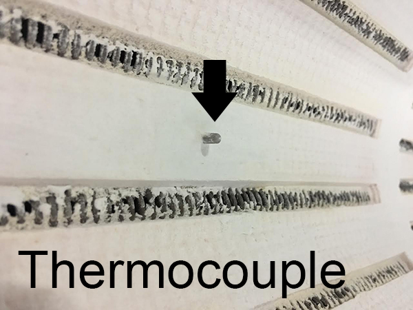
Thermocouple | |
Temperature Control
|
• Three precision digital temperature controller with 30 programmable segments and +/- 1 ºC
accuracy- • Safety protection of over-temperature and broken thermocouples are integrated
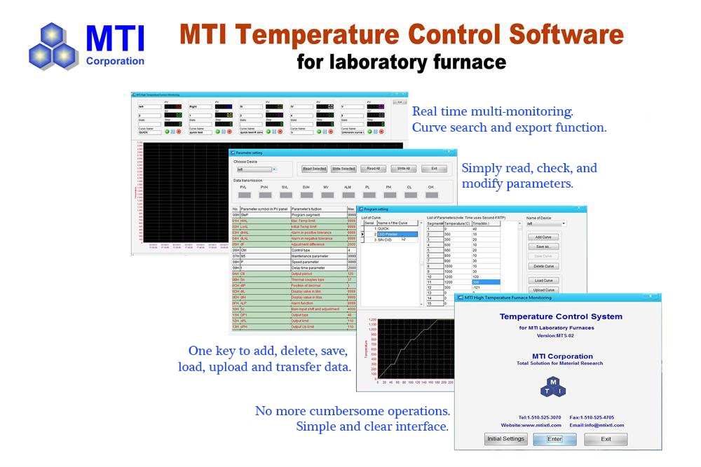
- • PC control software is available at extra cost
- • Eurotherm precision temperature controller with +/-0.1°C accuracy is available upon request
at the extra cost.
|
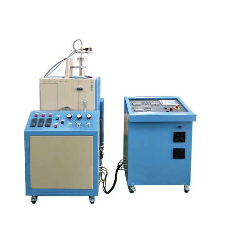
Control Unit

|
• Control panel is separated from the furnace for safe operation- • Temperature, pressure, and gas flow rate are controlled via the touch screen panel.
|
Process Vessel |
• Made of Nickel-based superalloy- • Vessel Size: OD 60 x ID 52 x L1200 (mm)
- • Working gasses: O2 and inert gasses such as N2, Ar, and He
- • In or der to melt the alloy or compound which contains the element that is evaporated easily,
you may put the sample into a graphite or BN tube with a screw cap as Pic. below the middle
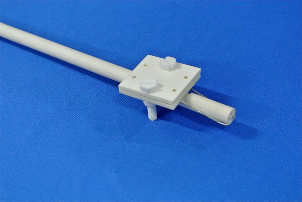
( ( the crucible is available upon request ) - • To fix the sample tube in position during the swing, two ceramic or stainless steel rod with the
thermal block is built in the flanges ( see picture right below ) - • Warning: Never put the sample inside the tube directly without crucible or isolated foil to avoid
sample react with tube alloy. - • Attention: Processing tube is a consumable part. Please click the photo below to order a
replacement or a spare one
-
  
|
Pressure Sensor and Valve
|
• Pressure gauge with range of 0 – 25 MPa and over-pressure alarm is installed
(downstream side)- • Pressure control valve with a working range of 0.2 – 15 MPa is installed (the upstream side
with 1/4" BSPP venting port) - • If the measured pressure reaches the high-pressure alarm value, the pressure control valve
will be opened until the pressure drops 0.2 MPa (2 bars) below the alarm value - • The manual pressure relief valve is installed for manual pressure control and relief
(the downstream side with 1/4" BSPP gas outlet port)
|
High-pressure relief valve
 |
• Safety pressure relief valve is recommended (the upstream side with 1/4" NPT venting port)- • Please info us your application temperature and we will pre-set the release pressure for you.
For example, you need to heat to 800C, the Max working pressure should be 140 bars, we will
pre-set the relief valve to 140 bars.
|
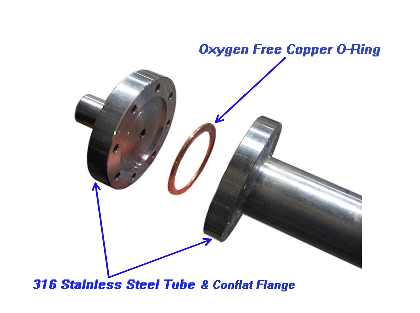
Flange and Fitting |
• A pair of 63 mm CF type flanges are included. Please use a torque wrench (optional, not
included) to avoid over tightening the flange bolts.- • 2 pieces of copper O-rings (99 mm OD x 82 mm ID x 2.2 mm thickness) are included.
Please order extra copper O-ring as consumable parts - • A pair of cooling fans are included for air cooling the flanges
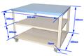
- • One mobile cart with installation holes is included for easy setup and immediate use
|
Dimension | |
Optional Parts
(with extra cost)
|
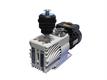
• Please order heavy-duty rotary vane vacuum pump (7.8 CFM, 240 L/min) – EQ-YTP-50 for
low vacuum operation (Pic #1)- • If high vacuum operation is needed, please consider the turbomolecular vacuum pump
station – EQ-PV-HVS2 (Photo #2) - • Gas flow control system is available upon request (Photo #3)
- • Please use a torque wrench (optional, not included) to avoid over tightening the flange bolts
(Photo #4) - • To measure the electric properties of thermoelectric ceramics under high pressure & high-
temperature, please order alumina fixture and high-pressure electrical feedthrough
(10 MPa max) with the furnace at extra cost (Photo #5 & #6)
 1 1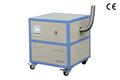 2 2 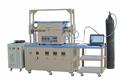 3 3 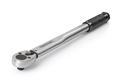 4 4
 5 5 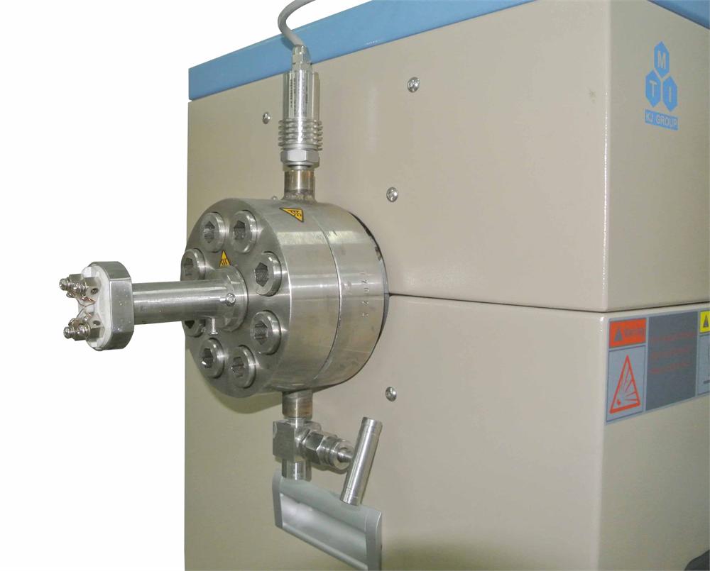
|
| Operation Instruction | 
|
Safety Notes

|
• Ni-based superalloy (Waspaloy or equivalent) is a reliable material which can be used under
high temperature and high pressure. It has excellent ductility and tensile properties. Only
creep deformation happens under overpressure, and cracks are usually formed at the center
of the tube to release the pressure. Brittle fracture and tube explosion will not happen.
Left pics shows Ni-based Superalloy processing tube under overpressure test
- • DO NOT overtighten the flange screws as this may cause permanent damage to the flange
or screws. Please refer to the instruction about proper torque for installing CF flange bolts.
We recommend you to use a torque wrench to tighten the screws with the flange
- • DO NOT operate the furnace at a temperature/pressure above the safety limit that MTI
recommends
- • Extreme caution should be exercised while operating within the vicinity of the high-
pressure furnace. The operator should NEVER stand in front of the flanges, gas inlet/outlet,
or the pressure relief valve while the tube is pressure loaded! NEVER face on the
gas inlet/outlet and the pressure relief valve to avoid injury from high pressure, hot gas
discharge
- • Attention: A two-stage pressure regulator must be installed on the gas cylinder to limit the
pressure for safe operation. Please click here to learn how to install the gas regulator.
- • For the use with flammable, toxic or corrosive gasses, you must contact
MTI engineering group for the consultation to know all the prerequisites
and precautionary measures
|