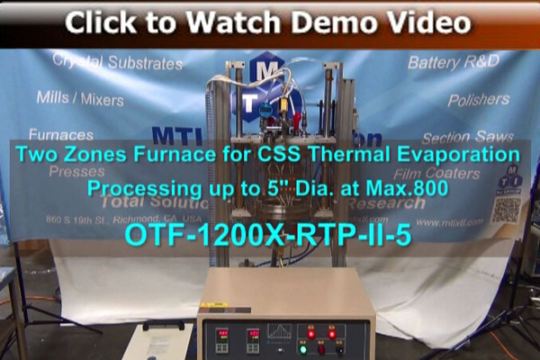
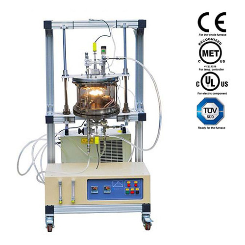
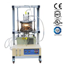
Furnace structure & Vacuum Chamber
 |
• Dual Heater, two temperature controllers, two-channel gas flowmeters are integrated into a mobile
aluminum alloy frame- • The chamber is made of high purity fused quartz tube
- • Quartz tube size: 11" OD/10.8" ID x 9" H
- • Carbon fiber felt as thermal insulation
- • The vacuum flanges are made of Stainless Steel 316
- • Overall dimension: 850(L)×745(W)×1615(H) mm
|
Vacuum Flanges
  |
• Top Flange with one KFD-25 vacuum port and two gas outlets (1/4" pipe required) can slide up
or down manually to load and unload substrate and evaporated material easily- • Bottom flange has one KFD-25 vacuum port with two gas inlets (1/4" pipe required) and needle
valves - • Flange is sealed by double silicone o-rings and can achieve maximum vacuum pressure of
10E-2 Torr by a quality mechanical pump and 10E-5 Torr by a molecular pump (vacuum pump
is not included, please order separately) - • Precision anti-corrosion digital vacuum gauge is in standard package (Since 2016.03.24).
|
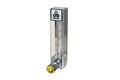
Gas Flow Meters
|
Two float-meters are installed on the control panel with measurement range of:
- • 16 -160 mL/m
- • 400 - 4000 mL/m (for purging purpose)
|
Heater and Sample Holder

  |
• Two shortwave IR lamps as heating elements for fast heating.- • The distance between two heaters is adjustable from 10 - 50 mm
- • The heaters are made of stainless steel with water cold jacket to reduce heat radiation and
allow for fast cooling - • 3" round wafer holder is built in with top heater to load substrate
- • One high thermal conductive AlN plate (3"Dia x 0.5mm Thick) is included, which shall put on
the back of substrate to make it heated uniformly - • One 3" graphite plate can be used alternatively for AIN plate, please click the picture below to
order. - • Halogen Light Heater replacement is available at extra cost, please click here to order.
|
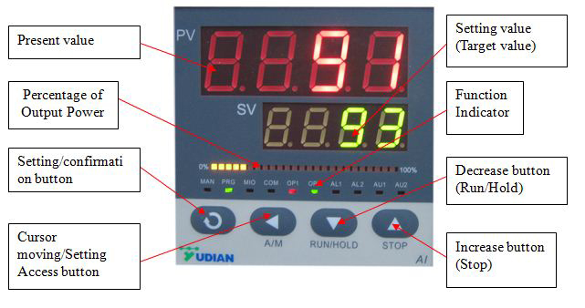
Temperature Controller
|
• Two precision digital temperature controllers with 30 segments programmable offer
independent controlling of top and bottom heaters- • Each controller has PID auto-tune function to protect heaters from overshooting and alarm
function to avoid overheating and thermal couple broken - • PC communication interface & software is installed for (click picture below for details) recording
temperature profile shown as below
|
Working Temperature
|
• Maximum temperature for each heater: <= 650ºC- • Maximum temperature difference between two heaters: <= 300ºC depends on the spacing
between two heaters: - º Spacing 30mm Max. temp difference: 315ºC @ heating bottom only
- º Spacing 40mm Max. temp difference: 350ºC @ heating bottom only
- º Spacing 50mm Max. temp difference: 395ºC @ heating bottom only
|
Heating & Cooling Rate |
• Heating: < 8ºC/s ( heating single heater only )- • Cooling: < 10ºC/s (600 - 100ºC) Max.
|
| Thermal Couple | Two K-type thermal couples (exposed) are installed on top and bottom heaters separately |
| Working Voltage | 208 - 240VAC, single phase, 20A air breaker |
| Power Requirement | 2200W total ( 1100W for each heater ) |
Optional
|
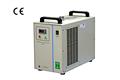
• One vacuum pump is required. Please order separately by clicking the first picture from the left
below. Vacuum level can reach < = 10E-2 torr by mechanical pump - • If you run corrosive gas, please consider to use anti-corrosive dry pump is shown in the second
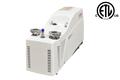
picture from the left below ( Pfeiffer pump from Germany ) at extra cost - • You may order a recirculating water chiller for saving water source separately
- • You may choose digital MFC gas delivery system by clicking the first picture from the right
below
|
| Warranty | One year limited with lifetime support ( Consumable parts such as quartz tube and heating lamps are not covered by the warranty) |
Laptop, software & WiFi Control (Optional) | |
Compliance |
• CE Certified- • UL / MET / CSA Certification is available upon request, additional charges will apply
- • Temperature controller is MET and CE Certified
   
|
| Application notes | Please read article: High efficiency CSS CdTe Solar Cell |
Operation Video & Instructions |
|
Warning
 |
• The tube furnaces with quartz tube are designed for using under vacuum and low pressure <
0.2 bars / 3 psi / 0.02 Mpa. Vacuum pressures may only be safely used up to 1000°C. The flow
rate for gasses should be limited to < 200 SCCM (or 200 mL/min) for reducing thermal shocks
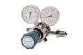
to the tube.- • Attention: A two-stage pressure regulator must be installed on the gas cylinder to limit
the pressure to below 3 PSI for safe operation. Click here to learn the installation of a gas
regulator.
|
Reference Articles | |


