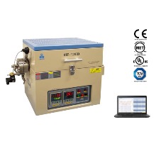
Furnace Structure

|
• Double layer steel casing with air cooling.- • High purity fibrous alumina insulation for max. energy saving.
- • The aluminum heat sink on processing tube to ensure pressure flange and fitting < 80°C
- • All Electric parts are UL certified and ready to pass TUV, CSA, and UL certificate
|
| Power | 2.5KW |
| Voltage | AC 208 - 240V Single Phase, 50/60 Hz |
| Max. Temperature | 1100°C |
| Max. Heating Rate | <= 30°C/min |
Material and Size of Pressure Vessel


|
• Special Ni-based Superalloy: ( Waspaloy or equivalent )- • 55 mm O.D x 20 mm I.D. x 580 mm Length
- • 1/4BSPP fitting is installed at the end of the flange, and 1/4" high-pressure stainless steel pipe
shall be connected to the fitting. - • Please click the picture below to see the detail of the pressure vessel
 Exterior Exterior  Interior Interior
- • Warning: Never put a sample inside tube directly without crucible or isolated foil to avoid
sample react with tube alloy. - • Attention: Processing Tube is a consumable part, you can click the picture below to order
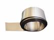
replacement or a spare one. - • Copper Gasket Size: 27.2mm O.D x 20mm I.D x 2mm thickness
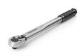
- • The optional torque wrench is available here to avoid overtightening the flange bolts. The
suitable tightening torque for 55 ODx 20 ID x 580 L (mm) is the 40-foot pound.
|
Compatible Gas and Crucible
|   
|
| Heating Zone length | 250 mm ( single zone ) |
Temperature Uniformity |
• Constant Temperature Zone length: 50mm within +/-1°C and 70mm within +/-2°C in- • Click the picture below to view the details of the Temperature Distribution Curve and Testing:
  Temp. Control ( left meter ) Temp. Control ( left meter )
|
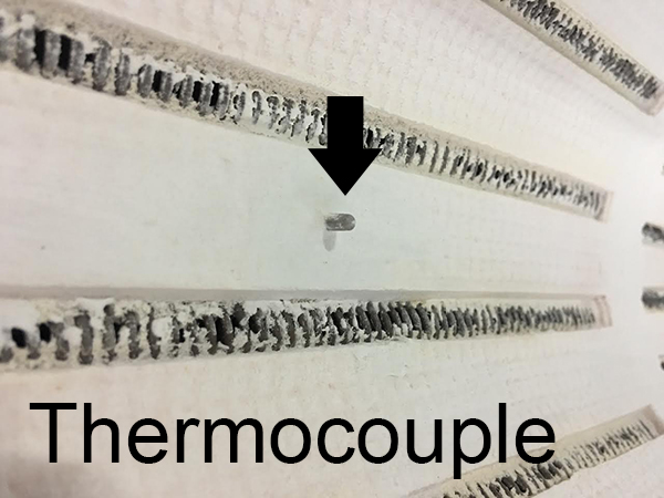
Thermocouple
|
Omega 3mm OD K Type with high-temperature tolerance (220°C) connector |
Temperature Control |
• MET certified 30 programmable segments for precise control of heating rate, cooling rate and
dwell time.- • Built-in PID Auto-Tune function with overheating & broken thermocouple broken protection.
- • Over-temperature protection and alarm allow for operation without attendant(s).
- • +/- 1 ºC temperature accuracy.
|
PC Control
|
• A brand new laptop with pre-installed & tested software included for immediate use.(Laptop is
included since 9/10/15) - • Pre-installed MTS-02 Control Software is included for controlling and displaying temperature
and pressure by PC at a remote location. - • Please don't try to buy a furnace without a computer because of liability issues
  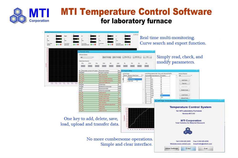  
EQ-MTS02-YP Software Download
|
Pressure Sensor and Display |
• Precision high pressure sensor (Pressure measurement range: 0~25Mpa) installed on pressure
vessel.- • The pressure sensor is installed in the flange. The pressure will be displayed in the pressure
controller in the front panel of the furnace. - • The alarm system is built in the pressure controller which allow the user to set up the high and
low limit point of pressure. When the measuring pressure exceeds limit point, the alarm strobe
and whistle will be activated for the warning. - • When the pressure reaches the alarm set point (Max.15Mpa), the pressure inside the vessel
will be released via the solenoid valve installed on the flange.
For Max.pressure >15 Mpa, please shut off the manual needle valve nearby the solenoid valve. - • Optional: Adjustable High-Pressure Relief Valve 1000 - 10,000 PSI (7 - 70 Mpa), click picture
below right to order.
Pressure Display(right)) flange assembly High-pressure Relief Valve
|
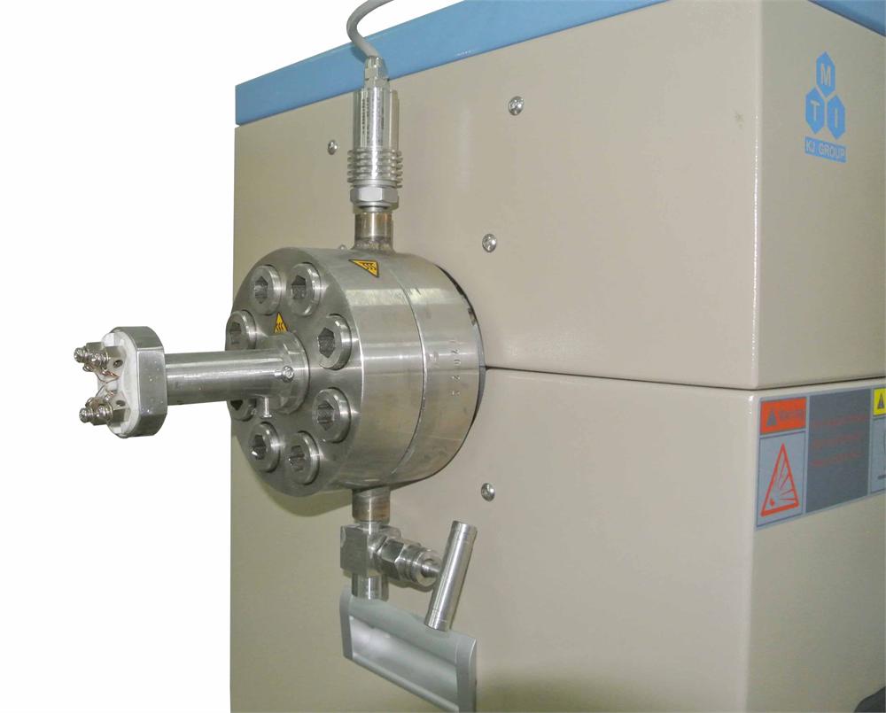
Pressure Fitting |
• One Super-alloy flange is included.- • One Aluminum heat radiators are installed in front of the flange to keep flange below 100oC
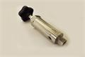
- • A high-temperature pressure transmitter, MTI-ZQ-GW is pre-installed with flange
- • One solenoid valve(Max.15Mpa) is pre-installed.
- • The safety pressure relief valve is available to be installed at the downstream side.
Please click here for details.
|
Optionals |
• You may order four Pt wire ( 0.35 mm dia ) feedthrough to install the furnace for measure material
electric conductivity under high pressure up to 1100oC at extra cost.- • 10 mm Sapphire window can be installed on the flange for Ramman beam under high pressure at
extra cost ( click picture below right to see detials) - • To measure the electric properties of thermoelectric ceramics under high pressure & temperature
conditions, please order alumina testing fixture and high-pressure electrical feedthrough (10Mpa
Max.) with the furnace (additional fee will apply).
-
|
Working Pressure vs temperature |
Allowable pressure (SF = 2)
| Heating temperature
| | Max. 3046 PSI (21 Mpa) | 800°C | | Max. 1813 PSI (12.5 Mpa) | 900°C | | Max. 914 PSI (6.3 Mpa) | 1000°C | | Max. 610 PSI (4.2 Mpa) | 1100°C |
The allowable pressure is calculated based on Barlow's formula. S = yield strength. Safety factory= 2
Click to download GH747 nickel-based alloy datasheet
Warning:
- • Please set up a pressure alarm point in digital pressure display before the operation
- • Must install a pressure regulator on the gas cylinder to increase pressure gradually.
|
| Heating Element | Fe-Cr-Al Alloy doped by Mo |
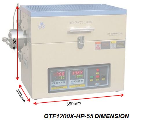
Dimensions |
550 x 380 x 520mm  (click to enlarge the picture) (click to enlarge the picture)
|
| Net Weight | ~45Kg |
| Shipping package Dimensions | 45x45x35 inch |
| Shipping weight | 200lbs |
Warranty |
One year limited warranty (Consumable parts such as o-rings and heating elements are not covered by
the warranty, please order the replacement at related products below.)
|
Certificate |
• CE Certified- • NRTL or CSA certification is available at the extra cost
 
|
Operation Instructions |
 
|
Application Notes |
Hytort Application, or named Hydroretorting of Shale Oil is a process developed by IGT to double the yield
of shale oil and hydrocarbon gasses. Please click underlined to view research paper.
|
Safety Notes

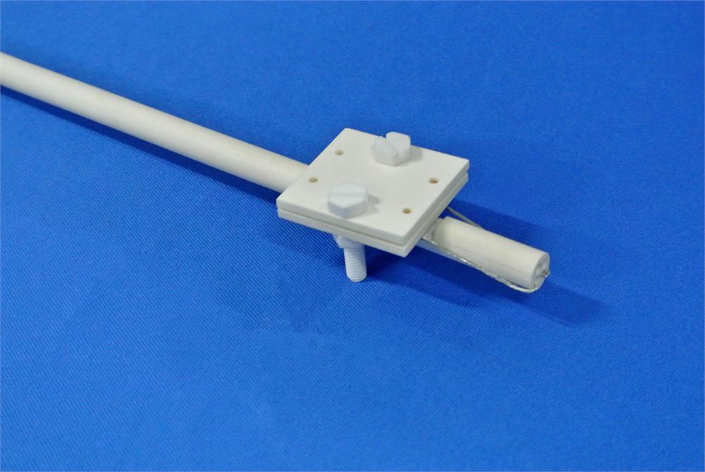
The picture shows Ni-based
Superalloy ( Waspaloy or
equivalent) processing tube under
overpressure test.
|
• Ni-based Super-alloy ( Waspaloy or equivalent) is a reliable processing tube which can be used
under high temperature and high pressure. It has excellent ductility and tensile property so only
creep deformation happens under overpressure destruction test and following by a crack formed
(usually at the hot zone at the center of the tube) to release the pressure. Brittle fracture won’t
happen in the overpressure destruction test which means no tube explosion will happen under- • Please never use ordinary SS tube to connect to gas-inlet for using > 5Mp pressure.
- • Attention: For the use with flammable, toxic or corrosive gasses, you must contact MTI
engineering group for the consultation to know all the prerequisites and precautionary measures. - • Attention: A two-stage pressure regulator must be installed on the gas cylinder to limit the
pressure to below 3 PSI for safe operation.
Click here to learn the installation of a gas regulator. - • Do not over-tightening the flange screws as this may cause permanent damages to the flange or
screws. Please refer to the instructions about proper torque for installing CF flange bolts.
We recommend you use a torque wrench to tighten the screws with the flange. - • Warning: Never put a sample inside the tube directly without crucible or isolated foil to
avoid sample react with tube alloy.
|